Monday, September 28, 2009

Engine Controls and Revised Canopy Latch Plates


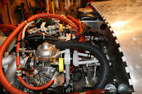
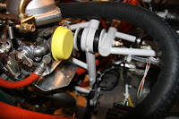
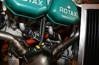
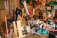
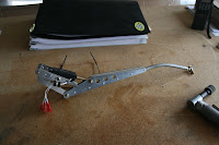
Did really nothing on Saturday. On Sunday and Monday, I fitted the new canopy latch and then started the installation of the engine controls. Was kind of difficult getting the cables thru the grommet in the firewall. The grommet wanted to dislodge itself. Would have been easier to lube the cables but the plans for some reason tell us not to do it. I am short one nut that secures the throttle cable to the carb bracket. Will look for it on Tuesday.

Down to odds and ends.

Time Sunday and Monday - 6 hours

Friday, September 25, 2009

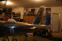
Installed HS, Completed the Tailcone Fairing, Installed the Trim System, Lower Cowling Trimmed for Exhaust, Trimmed Exhaust Pipe


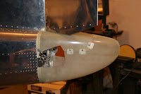
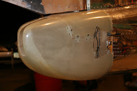
Over the past few days, I mounted the HS and was thus able to align the tailcone fairing. Drilled the holes in the fairing and the tailcone for the nutplates.

I had to remove about 1/8" of material from the HS skin at the aft end of the tailcone fairing. The plans want 1/8" between the HS skin and the tailcone fairing.

Fabricated the trim motor bracket and installed the trim motor and checked its operation. I have a problem setting the speed of the trim motor to the specification in the plans. More on this below. Also had to do a bit more sanding on the slot in the fairing as the trim rod was closer than 1/8" to the fairing.

Removed the HS and drilled the rivet attach holes for the nutplates and riveted them to the tailcone. 3 full days, about 22 hours to complete the tailcone fairing work.

Also, attached the lower cowl and checked the exhaust pipe fit. I had to open up the hole as the pipe was not centered. Then marked and cut the exhaust pipe to 4".

Trim Motor Issue as Posted on VAF. Hope to find a solution, soon!!

"Problem-Setting Trim/Servo Motor Speed"

The fastest trim speed I can obtain at a battery voltage of 12.3 VDC (as measured with a DVM at the battery) is 40 seconds (stop to stop). This is with the potentiometer at its stop. The trim motor merely buzzes with the pot fully in the other direction. The plans call for a min speed of 30 seconds at 12.0 VDC. The trim motor sounds as though it is laboring (wha-wha sound).

ANYONE else having this problem?? Has anyone solved the problem??

I measured the resistance of white wire and the white/red wire (power to the motor) from the tail to the 37 pin connector behind the panel and each is 0.9 ohms. So the wires and all crimps are good.

I have attached a battery charger and with a battery voltage of 13.8 VDC (at the battery), the trim speed is 31 seconds.

I have measured the DC voltage at the running servo with a DVM. The voltage is 5.0 VDC. From another post, I understand that the control panel board produces a pulse width modulation signal. A lower voltage is to be expected as the DVM is measuring an average of the chopped signal. I do not have a scope to view the waveform.

With the trim motor attached to a DC power supply, the trim motor speed is 12.0 seconds at 12.0 VDC and 10.0 seconds at 13.8 VDC.

I have talked to support at Van's and they have acknowledged others are having the same issue, but, could not suggest any other testing other than replacing the switch panel.

Has anyone replaced the switch panel and obtained better results??

Do the servos vary? Has anyone replaced the servo and obtained better results?

Time Over the Past Few Days - 24 hours

Tuesday, September 22, 2009

Vertical Stab, Rudder. Tailcone Fairing


On Monday, fabricated the fairings for the vertical stabilizer and the rudder and riveted them. Before mounting the vertical stabilizer to the tailcone, I attached the rudder and checked for any interference. (This was the subject of a VAF post). Had an interference on top at the fairings and the left VS skin hit the rudder skin when the rudder was full left. Had to take about 1/32" off of the aft left side VS skin and some off the VS fairing at the interference. Mounted the VS and rudder on the tailcone.

On Tuesday, started the tailcone fairing. A lot of cutting and sanding. All went well and am about 75% complete. Will have to mount the HS on Wednesday to set the final alignment of the fairing and check the clearances.

Time Yesterday and Today - 13 hours

Sunday, September 20, 2009

Wedding Rehearsal & Dinner on Friday--Wedding on Saturday


Very little RV-12 work is planned for Friday, Saturday and Sunday.

One of my daughters, Heather was married this weekend. Everything went VERY well. Heather and my wife Renee did a phenomenal job at planning the entire affair. Heather and Brendan (who works at Boeing in Seattle as an aero engineer) were very happy and all had a good time.

The wedding reception at the Davenport Country Club was just something else.

Friday, September 18, 2009

Spinner, Oil Lines, Then the Exhaust System


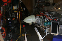
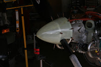
Over the past 4 days, I installed the spinner, installed the oil lines and then installed the exhaust system.

The alignment of the spinner and then attaching the nutplates and attaching the inserts took me 2 days. A lot of fitting, sanding to get all of the parts to fit.

Installed the oil lines, but, may change them again, because the oil line that runs to the left side of the oil radiator is rubbing against the crankshaft sensor at the rear of the engine. I do not think that is a good idea.

RTV'd the gasket material to the inside of the cowling opposite of the coolant radiator.

Installed the cowling to ensure all parts fit. Getting the cowling on this time was a bit more difficult because you have to compress the gasket material at the coolant radiator. Was happy for now with the spinner to cowl fit. It is perfectly concentric. The minimum gap is 0.060" which should be OK for now. Scott McDaniels indicated that 0.060" was a good starting point. A bit more can be removed from the aft end of the spiiner and plate if need be.

Removed the cowling and installed the exhaust system.

Also removed the fuel tank flange (the one with the bad threads) from the tank, fished out the 6 rivet heads and installed the new fuel tank flange. Used a very thin putty knife to pry the old flange off of the tank. Had another dose of sealant again!! Love that sealant!

Time Over the Past Days - 24 hours

Monday, September 14, 2009

Pitot Tube Installation, Completed the Electrical Installation, Spinner Trimming, Fuel Hoses, Prop Installation, Heater Door and Cable


Pitot Tube Installation, Completed the Electrical Installation, Spinner Trimming, Fuel Hoses, Prop Installation, Heater Door and Cable

It is getting harder and harder to keep the log up to date. Over the past days fabricated and installed the pitot tube at the front of the engine. The plans tell you to screw the pitot tube into the plastic block to a measurement of 1.5". The pitot tube bottoms out in the plastic block at a dimension of about 1.25". Screwing it in any further would damage the threads in the plastic block. The tip of the pitot tube will then end up, 0.25" more forward.

Received a care package from Van's containing some of the missing spage lugs and barrel connectors. As such, I was able to complete the electrical installation. It is nice being able to turn on the master switch, the avionics switch and watch everything come to life.

Trimmed the spinner to the scribe line. I had two scribe lines on the aft edge of the spinner. Scott told me to trim to the most forward scribe line making the spinner the shortest if it was sitting upright on the table. This worked very well. One caution, when making the cuts for the prop on the spinner, cut right down the middle of the scribe line. As such, the filler pieces you will make out of this scrap will be large enough.

Received the VA-215 fuel hose in another care package. Installed it on top of the banjo fitting. It runs to the fuel pressure sensor and the fuel return line.

Installed the prop per the Sensenich prop manual. The drawing in the plans is not quite accurate as it does not portray the bushings that have to be inserted into the prop flange on the engine.

Then worked on the heater door. When cutting the sheath on the cable, the plans tell you to trim it to a dimension of 2 27/32". Dry fit the components here. The sheath has to remain inside the F-1210 rod when the heater door is fully closed. My final cut was at a dimension of 3.1" to 3.2". Cut the sheath with a cutoff wheel in the Dremel.

Then I HAD to check the fit between the cowl and the spinner. It really does fit very well. Have a slightly tighter gap on top than the bottom.

And took a day off from the build for some flying at the Davenport airport!!

Time Over the Past Days - 26 hours

Wednesday, September 9, 2009

Fuel Pump Problem, Set ALL Audio Levels, Brakes Bled, Cooling Duct Fabrication and Fiberglass


Over the past few days, I fabricated and fiberglassed the cooling duct attached to the lower cowl and detoured for a day to solve an electrical problem, my fuel pump did not work.

First, the fuel pump problem. Mine did not work when I powered up the electrical system (with the voltage regulator UNPLUGGED). (There is another problem related to the voltage regulator/rectifier as 2 fellow builders have observed smoke coming from the regulator/rectifier when they powered up the electrical system.) With regard to my fuel pump problem, with the assistance of John Bender, we determined one of the wires in the 37 pin tunnel harness connector was in the wrong position. The pin was in position 30 and it should have been inserted into position 29. This problem was confirmed by Stein via a post on the VAF forum. The early harnesses were mis-wired in this manner. The subsequent harnesses should be OK.

Since I was now implanted in the electrical mode, decided to check the rest of the electronics and electrical system. All seems to function normally. Adjusted all of the audio level potentiometers on the rear side of the switch panel in accordance with the plans. The only potentiometer left to be set is the pot for trim speed. It is hidden under the Dynon. Getting a screwdriver on this pot requires partial removal of the left panel section. Otherwise there is NO way to get a screwdriver on the potentiometer. (This was confirmed by a couple of fellow builders). The left panel section MUST be raised a bit and/or the upper part of the panel tilted aft. Then you can get at the pot with a screwdriver.

Then started working on the cooling duct. Trimmed the cooling duct and its adapter to the scribe line. Then after trimming it, and re-fitting it to the lower cowl a number of times, the cooling duct was cleco'ed in place. The adapter is to fit 0.25" from the face of the coolant radiator. Two days of work.

Today, I bled the brake lines in the morning (used the bottom up method with a hand pump oiler at the bleed valve, used Aeroshell 31), went flying in the early afternoon and then fiberglassed the cooling duct and the adapter to the lower cowl. Everything, including the upper cowl was then installed on the airframe. Such allows the fiberglass to cure to the correct shape.

Time Over the Past 4 Days - 27 hours (includes 8 hours to troubleshoot and correct the fuel pump problem)

Saturday, September 5, 2009

Continued with the Engine Installation


Over the past few days, fabricated and installed the heater door, the coolant radiator, the oil tank and the coolant overflow tank. The plans seem to be OK here. Then started to look at the frame that sets around the oil cooler radiator. The plans here are VERY poor.

If you do not want to get frustrated, be VERY CAREFUL when following the plans on page 49-09 & 49-10. They may be partially correct BUT the descriptors used are not consistent, which increases the confusion level to the maximum.

Dry fit all of the components and then mark which hole has to be C/S and which hole has to be dimpled. The rivets have to be flush adjacent to the oil cooler AND the rivets have to be flush where they contact the fiberglass cooling shroud.

I read the plans initially, and marked which side had to be C/S or dimpled and STILL got it wrong. I am so glad I read ahead here.

Dry fit the components, mark each hole and the side of the hole that has to be C/S or dimpled and READ AHEAD.

These two plan pages are POOR!!!

Time over the Past Days - 16 hours

Wednesday, September 2, 2009

Engine Hung!


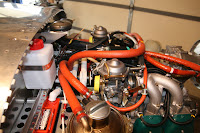
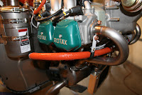
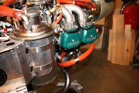
Yesterday, I glued the cooling shroud to the engine using grey sensor safe high temperature RTV. Looks better than the Red RTV and is rated to the same temperature. Then reassembled the engine components that were removed the day before. Then, removed each of the carbs and attached the drip pan under each carb after riveting them and sealing the bend holes with fuel tank sealant. The drip pan MUST be for "drips" but seems to also shield the carb from the exhaust manifold.

This afternoon, I drilled the lower engine mounts to 3/8". Slow going, even with brand new cobalt drills. Deburred the holes and was ready to put the engine hoist to work. With the help of a couple of chapter members, hung the engine on the plane. It helped to have 6 hands for the engine installation. Two of the hands belonging to my son, Adam, who again, crawled in the cabin to tap and hold the engine bolts.

The engine sure looks small mounted to the firewall as opposed to it being on the workbench.

Time Yesterday and Today - 10 hours