Hope all had a good Christmas. Had a chance to get back to work today on the tailcone and started preparing the components for the horizontal stabilator.
On Page 09-02 the plans require quite a bit of countersinking. Figure 1 shows two machine countersinks in each HS-1211 spar cap for two CS4-4 rivets BUT there is no corresponding step in the plans that tells you to countersink these holes. Also, I believe, the plans should tell you to countersink for the CS4-4 rivets using the "special" 120 degree countersink as the CS4-4 rivet has a 120 degree head. CS4-4 rivets are also used on the HS-1202 spar and HS-1203 spar. This research took me a bit of time, but, found the answer via the VAF forums and other sites.
Also a CS4-4 rivet cannot be found in the catalogs. Must be Van's nomenclature for this rivet type. Via the forums I found the following info:
In fact, here is the cross reference I found via research. The BSP and BSC rivets can be found in the catalogs (Aircraft Spruce shows the specs).
BSP-43 will sub for a LP4-3
BSP-44 will sub for a LP4-4
BSC-44 will sub for a CS4-4
Also suggest reading ahead and countersinking all of the 3/32" rivet holes in each of the components and then changing/setting the countersink cage for the 120 degree CS4-4 holes. It takes me a while to set the cage for the different countersinks. Bet some of you have more than 1 cage!!
Anyone know if a 120 degree dimple die set is required anywhere in the tailcone or fuselage plans?? Also, let me know if the above is in error. Will continue deburring and priming the parts on Monday.
Reading the Sunday paper is kind of depressing as it seems all of the news related to 2008 is bad/negative. Kind of disagree, as in 2008 WE are building, one heck of a plane, the RV-12.
Time - 3 hours
Sunday, December 28, 2008
Tuesday, December 23, 2008
Anti-Servo Trim Tabs are Complete


Completed both the left and right anti-servo trim tabs today. No real problems with the assembly. I drilled the hinges using the drill press. Did notice one of the holes in the template was elongated and did not use that hole any further. Keep an eye on the condition of the template. Two of the templates are supplied with the kit, maybe with this in mind. The second trim tab went much faster than the first, as usual. Did have to touch drill a couple of the holes on the hinges before riveting. Maybe to be expected as you are riveting three pieces of metal, one drilled with the template. The horizontal stabilizer is next. But it might have to wait until after Christmas. MERRY CHRISTMAS EVERYONE!!!!!
BigJohn on the VAF Forums had a good suggestion here. Here is his post.
Here's a suggestion for you fellows who haven't gotten to the AST section yet. I had a bad time with riveting the control horns to the AST ribs as called out in Step 3. It is very awkward getting the squeezer positioned behind the flange in the rib, which is already attached to the skin at that point. This, and my inexperience at that point, resulted in gaps between the riveted parts. Two attempts resulted in the same problem, and damaged parts. It should be noted here that these parts have to be riveted tightly together, with completely flush rivet heads, in order for them to fit together when the AST halves are mounted to the stabilator hinges on Page 11-04.
Anyway, I ordered new end ribs and control horns from Van's, and started over. This time I riveted the ribs and horns together BEFORE riveting the ribs into the end of the servo tabs. This simplifies the procedure and makes it very easy to get the squeezer positioned properly for a good tight rivet set. I then installed the completed assemblies into the ends of the AST's and riveted using the LP4-3 rivets. In two spots behind each horn, I used the little wedge tool and the hand squeezer because the rivets go in quite close to the horn. After all was said and done, the AST assemblies now fit prefectly onto the completed stabilizer hinges, but believe me, there is no room to spare!
Time - 6 hours
Monday, December 22, 2008
Rudder is Complete


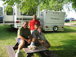
Assembled the rudder components today. All went very well. The only hint I can add is to insure the skins overlap as per the plans at the leading edge of the rudder before you start to rivet the skins. If you follow the plans step by step and do not ensure the overlap is correct, I think it would be next to impossible to correct. (That is, without drilling out a bunch of rivets.) The solution is to always read ahead during the assembly process. The skeleton and the finished rudder is shown in the pictures. Heather, my daughter, and, Brendan, her fiance are holding the rudder up next to the vertical stabilizer.
Time - 4 hours
Saturday, December 20, 2008
Scotchbrite Wheel/Mar-Hyde Hint
Did not accomplish any work on the rudder on Saturday, as Renee and I went to Chicago-O'Hare to pick up Heather and Brendan. Blizzard conditions during the drive to and then back home on I-88. Left at 2PM, arrived home at 11PM.
Wanted to pass this tip. My scotchbrite wheel in the bench grinder had developed two fairly deep grooves making edge finishing a bit difficult. To true up the wheel, a belt sander with 80 grit paper held against the running scotchbrite wheel trued the wheel and eliminated the grooves in about 1 minute. Much better than using an old file, and, one does not have to worry about depositing a dis-similar metal in the scotchbrite wheel. The same will work with the 1" wheel in the die grinder.
Also ordered a quart of Mar-Hyde self etching primer. Have the rattle can variety but not the paint can version. Should be much easier to use during the winter months. I'm going to give it a try to prime the mating surfaces. Have been using a small throw away foam brush.
Friday, December 19, 2008
Vertical Stabilizer is Complete

Finished skinning the vertical stabilizer without any problems. Checked all of the nutplates before skinning. (Thought that was a good idea). The fit of the skin was very good and did not have any buldging of the skin at the leading edge. Was pretty aggressive when I rounded the ribs that could have dented the stabilizer skin near the leading edge. Riveting was relatively slow because the plans say to slowly rivet from the leading edge on both sides working toward the trailing edge. Worked OK, but riveting took a bit of time. Will start the rudder on Sat. Have completed a bit of that section while I was waiting for parts. Will visit ORD on Sat. also.
Time - 4 hours
Thursday, December 18, 2008
Vertical Stab Skeleton Complete, Prep of the Skins


Yesterday I completed the vertical stabilizer skeleton. If you look at the pictures carefully, you will see I decided to prime the spar because I scratched the alclad quite a bit during the assembly process. Primed it with Marhyde. The other mating surfaces are primed with SW P60-G2. The instructions tell you to cover the holes where one should not rivet. Let me tell you, this is not a bad idea. Had to drill out two of the LP4-3 rivets because I did not take this advice. Today, I deburred both of the vertical stabilizer skins and riveted the nutplates to the skin which will allow attachment of the lower leading edge.
Before skinning, I am going to run a bolt or screw after coating with beolube into each of the nutplates to ensure I do not a problem with any of them (binding). Easy to replace them now, if necessary. The four nutplates on the spar would be nearly impossible to replace later.
Completion of the vertical stabilizer is scheduled for Friday. Then on to O'Hare to get my lovely daughter and her future husband.
UPDATE: From the VAF Forums
"I found another possible gotcha on page 06-04. Before you rivet the nut plates to the VS-1202 front spar (step 6.), be sure and final drill #12, the four holes in the VS-1202 front spar and the two corresponding holes in the front of the VS-1208 lower main rib that are for the AN3 bolts. The plans don't tell you to do this, but it is obvious that it should be done. I'm going to call VANS and bring it to their attention." Steve
Time - 5 hours
Tuesday, December 16, 2008
Vertical Stabilizer Spar Caps


Match drilled the right and left lower and upper spar caps to the vertical satbilizer spar without any problems. There is a lot of match drilling to do here. The first picture shows one upper and lower spar cap drilled the other not yet match drilled. The second picture shows all 4 spar caps match drilled and deburred. Countersinking of the upper spar bracket was completed next. The third picture shows the countersinking of the holes in the upper spar cap. Because 2 of the holes are VERY close to the spar cap bend radius, you are not able to use the microstop countersink. I placed the countersink bit in the drill press and countersunk the 2 holes very slowly to the correct depth. Countersunk the required holes in the main spar and the front spar with the microstop cutter.
Time - 4 hours
Monday, December 15, 2008
Starting Section 6, Vertical Stabilizer and Section 7, Rudder


Am expecting a shipment from Van's today that will contain the backordered VS-1210 hinge bracket that will allow me to start on the vertical stabilizer. Until it arrives, I have started on Section 7, Rudder. Today, I constructed the R-1204 spar caps and the R-1205 hinge brackets. The spar caps were match drilled to the spar and the WD-1205 Rudder Horn was final drilled to the spar. The spar caps, hinge brackets and rudder horn were temporarily clecoed to the spar.
Late in the day the R-1210 hinge bracket arrived and thus was able to start Section 6.0, Vertical Stabilizer. Prepped the vertical stabilizer hinge brackets, inserted the COM-3-5 bearing and riveted the 3 parts of each hinge assembly together. I did not have a problem with the tip of the hinge bracket pulling apart or separating as mentioned on the VAF forums.
Time - 3 hours
Sunday, December 14, 2008
Priming of Vertical Stabilizer, Rudder, Anti-servo Trim Components Completed
It was 55 degrees today and tonight it will be 5 degrees. Was able to complete deburring of the components and primed the mating surfaces with Sherwin Williams P60-G2 wash primer. Lots of nasty fumes from the primer but luckily I was able to leave the garage door open today. Have not been able to spend a lot of time with the kit during the past week due to commitments. On Saturday, I spent about 3 hours deburring, and, today (Sunday) I primed the parts. Assembly of the vertical stabilizer, rudder, anti-servo trim tabs starts on Monday. The back-ordered part for the vertical stabilizer should also arrive on Monday. Thus, will probably start with the rudder.
Time - 4 hours
Time - 4 hours
Tuesday, December 9, 2008
Started Assembly of the Empennage

Started assembly of the empennage kit today, Tuesday December 9. The first step in the instructions has you build the wedge used for close quarters pop riveting. As I had already constructed the wedges with the wing kit, the step was not necessary. The second step has one separate and debur the VS-1210 bearing bracket. Guess what, after searching for the part under the workbench, I finally figured out the part was the only item that was backordered with the empennage kit. Thus, spent the day deburring the parts for the vertical stabilizer, rudder, anti-servo trim tabs. Will continue deburring parts and priming parts the next couple of days.
Also called Van's to check on the backordered parts. All of them will ship today, including another 2500 LP4-3 rivets as the original 10,000 will not be enough. Per the UPS tracking number, the parts will not arrive until next Monday. As such, deburring and priming the mating flanges will have to occupy my time.
Time - 4 hours
Sunday, December 7, 2008
Fuselage and Empennage (Tailcone) Kits Finally Have Arrived


After waiting for about 3 months after completing the wing kit I finally received both the fuselage kit and the empennage kit on Friday, December 5. My birthday was December 2, this is some BIRTHDAY present!! I have to compliment Van's because the combined shipment most likely saved me about $300. The shipment was contained in two manageable wooden shipping crates. Lots and lots of parts. Performed the inventory of the empennage kit on Saturday. One item was backordered, the VS-1210 bearing bracket and the parts listing indicated I would receive a separate shipment via FedEx or UPS containing two fairings, the upper and lower tailcone fairings. All parts, with the exception of those mentioned were accounted for. And, there was absolutely no damage to any of the parts. Van's is putting a lot of work into packaging and protecting all of the skins and the multitude of parts in the kits.
On Sunday, I performed the inventory of the fuselage kit. You would not believe how many parts are contained in the hardware kit associated with the fuselage kit. I would say there are about 2X compared to the wing kit or the empennage kit. One part, the F-1203J doubler was missing from the kit and four (4) AN3-7 bolts were backordered. Have to say, Van's has a darn good batting average. Of the 3 kits received to date, this is the first item missing from the thousands and thousands of parts received.
Quickly determined I was out of storage space thus had to negotiate with Renee to use the spare bedroom for storage. You DO have to have a saint of a wife to survive the building process. The picture shows the fuselage parts now residing in the spare bedroom along with the flaperons. I am more than ready to start assembly. Will most likely start the empennage assembly on Tuesday. Monday will be spent Christmas shopping with Renee.
Monday, November 17, 2008
Wing Plans Addendum and Hints from a Prior Posting
Wanted to ensure the following was referenced here as they are a good set of hints for those starting wing assembly.
Wing Assembly Hints
Wing Assembly Hints
Friday, November 7, 2008
Can You Modify the RV-12
Thought I would post this as it comes up in conversation quite a bit when builders gather.... (from the VAF forums)
Below is a reply from Joe Norris, Senior Aviation Specialist at EAA.
It's ALWAYS legal to modify an experimental aircraft. That's the nature of the experimental certification categories. The only time when it's not acceptable to modify an experimental aircraft is BEFORE the initial certification of an ELSA that's built from a Consensus Standard-compliant kit from an SLSA manufacturer. This certification category, under the authority of 14 CFR 21.191(i)(2) requires that the aircraft be assembled in accordance with assembly instructions provided by the manufacturer. Since this application requires a Statement of Compliance (FAA Form 8130-15) from the manufacturer, the only way that statement can be valid is if the aircraft is assembled strictly in accordance with the manufacturer's instructions.
However, once that ELSA gets its airworthiness certificate it is an EXPERIMENTAL aircraft just like any other, and you will find no regulation that restricts the modification of such aircraft. The only guiding document will be the aircraft's operating limitations (issued by the FAA as a part of the airworthiness certificate) which will require an approval process to be adhered to if a major change is made. This does not prohibit the change, but does put in place a specific procedure to approve the change.
There is no FAA document that specifically says an ELSA (or any other experimental aircraft) can be modified. The more important issue though, is that you can't find any regulation or guidance that would prohibit such modification. The maintenance and repair regulations found in 14 CFR Part 43 specifically do NOT apply to experimental aircraft, as stated in 43.1(b):
This part does not apply to any aircraft for which the FAA has issued an experimental certificate, unless the FAA has previously issued a different kind of airworthiness certificate for that aircraft.
This specifically states that the maintenance and repair regulations found in part 43 do not apply to an experimental aircraft. That being the case, there is no restriction on who performs maintenance, repair or modification.
I hope this helps to explain the situation. If not, let me know what further questions you have.
Joe Norris
EAA 113615 Lifetime
Homebuilders Community Manager
EAA—The Spirit of Aviation
www.eaa.org
See you at EAA AirVenture Oshkosh—July 27 – August 2, 2009
Monday, October 20, 2008
A Couple of New Tools


Found a couple of tools you might find useful.
Found a nice sanding drum at Menard's available in medium and fine grit. About $4 each. They are scotchbrite pads and sandpaper sandwiched together. 2.5" in diameter. Works well in the die grinder or drill press. An idea from John Bender.
Also found a 1" diamond tipped hole saw I found at Harbor Freight. Cuts a nice disc out of a scothbrite pad for use in the Dremel tool with the standard mandrel. Following JerryG's debur idea.
Wednesday, October 1, 2008
Sent Van's an e-Mail
Sent an e-mail today to Barb at Van's. My builder number is 120088. Will let you all know the projected delivery date for the fuselage. Ordered it at Oshkosh!
UPDATE: Fuselage Kit to be shipped the week of December 1 per Van's!! My birthday is December 2. My present from all!!
UPDATE: Fuselage Kit to be shipped the week of December 1 per Van's!! My birthday is December 2. My present from all!!
Monday, September 29, 2008
Rivets ??

So if there were 10,000 rivets in the box that Van's sent me, how many have I used during construction of the wing kit? Looking at the pictures, the rivets filled 3 of the Tupperware containers. I've used 55% of the rivets. 5500 rivets, so far. The pneumatic riveter from Avery has worked well!!
Finished the Wing Kit Today - Finished the Right Flaperon


Finished the wing kit, it has been 1 month exactly!!!!! I finished the right flaperon, and, as such, have completed the RV-12 wing kit. All went very well with no complaints. The biggest problem I had today was removing the blue plastic from the inboard nose skin. It took about 60 minutes to remove it, came off in about 100 pieces. Will attach the rod end bearings when I figure out where we are going to store the flaperons. Maybe one of the girl's old bedrooms! Do not have any more to add to the blog with regard to suggestions.
Want the next kit, the fuselage kit, ASAP.
This has, so far, been a good experience.
Time - 8 hours Total - 175 hours
Sunday, September 28, 2008
Finished the (1st) Left Flaperon Today


Was a bit concerned yesterday in setting the rivets on the A-1207-L actuation bracket. What worked well what was on the suggested tool list. I used the 1/8" rivet x 1/2" tall cupped squeezer and was able to set the rivets, even though they were quite close to the web of the bracket. Suggest to all to ensure the bracket is as close as possible the inboard nose rib and bracket assembly by inserting the AN3 bolt (not supplied) and using a nut on the other end to squeeze the 8 washers. (My suggestion, not Van's). Then match drill per the instructions, after, of course, ensuring the brackets are 90 degrees to the spar. Attached the pivot bearing brackets and continued with assembly.
The remainder of the flaperon went without a bit of a problem. Follow the instructions and the instructions as shown in the FIGURES. Had to touch drill one on the holes in the counterbalance but otherwise all of the holes in the skins lined up just perfectly.
To form the trailing edge skins of the flaperon, I bent them ever so slowly using a piece of 8" x 24" plywood with a short nap towel between the piece of plywood and the skin. If you go slowly, and use this method, you will get a nice bend to match the A-1205 main ribs and you will not end up with your handprints in the skin. Suggest starting with the bottom edge of the skin up. Go Slow! Do not press on the left or right edge of the plywood, do not put a crease in the skins. Go slow!.
Attached and riveted all of the trailing edge skins. Ensure you are hitting the ribs by feeling with your finger or using a flashlight. Then attached the nose skins. Follow the instructions when match drilling the A1210-L and R nose ribs. Ensure they are 90 deg to the spar, match drill with a #40 drill, insert a 3/32" cleco as you go and then match drill with a #30 drill inserting 1/8" cleco's as you go.
First flaperon is now complete. Looking down the edge, it is absolutely straight with no hint of twist. One more day (hope to finish the 2nd flaperon) and I am out of work! Where is the next kit?
Time - 7 hours
Saturday, September 27, 2008
Started Flaperon Assembly


Started the flaperon assembly today. I first drilled the inboard and outboard holes in the counterbalance tube after clecoing the parts and skin together. I drilled the holes in the tube using the suggestion of Jerry Greenberg. He drilled a dimple in the tube using the hand drill and then finished the hole in the drill press. This worked very well for all of the holes in the counterbalance tube. Then riveted the nose ribs to the counterbalance tube. Cleco-ed all of the parts together and then used the hand drill to dimple all of the holes in the counterbalance tube. Disassembled all and finished all of the holes in the tube using the drill press. Match drilled the nose ribs and have to confess that I elongated one of the holes in the skin here. Not bad but another lesson to be learned. When match drilling thru a skin into a harder material, ensure that the drill is vertical so it does not have a tendency to slip one way or another. Disassembled all and deburred all of the holes. Tried my best to debur the interior holes in the stainless steel tube using a round file taped to the end of a long dowel. Riveted the A-1208 bracket to the A-1210-L Inbd nose rib which I had separated earlier. Then attached and match drilled the pivot brackets and the actuation bracket to the spar. Removed all and deburred all holes.
Have a suggestion for Ken Krueger and the engineering folks at Van's. The outboard holes in the A-1207-L actuation bracket are a bit to close to the web of the bracket. I have not set the rivets yet but setting these rivets will be a bit difficult. Will be hard to get the manufactured head of the rivet to sit flush with the surface of the bracket due to interference of the bracket web. The last 4 photos show my actuation bracket (2 photos) and a photo from Jim Cone's website and Jerry Greenberg's website. All show the exact same condition. Will try to be careful when setting the rivets.
Time - 5 hours Total - 160 hours
Friday, September 26, 2008
Ready for Flaperon Assembly


Machined the last flaperon actuation bracket today. Have to say the 2nd actuation bracket looks a bit better than the first. This took about 3 hours. Then I cut the "dreaded" 30 angle in the pivot bearing brackets. Using the VAF forum suggestion, it was easy. Then scotchbrited the parts and cleaned the parts with acetone. Primed the non-alclad components with rattle can Marhyde, available from the local auto parts store (O'Reily). I primed all of the flanges with the Sherwin Williams wash primer. An update... A word of CAUTION, when fluting the flanges of the brackets, flute them exactly where the drawings say to flute. When you match drill thru the flaperon nose skins, the flutes will be extremely close to the match drilled rivet holes. Don't ask me how I know!!
Time - 6 hours
Thursday, September 25, 2008
Continuing with the Flaperon


Built the remaining 3 pivot bearing brackets from the supplied material. Took the suggestion of Jim Cone and used a slightly undersized drill to align the bracket in the drill press. Then bored the hole to a 1 inch depth using the correct drill size prior to tapping the hole in the bracket. Then I chucked the tap in the drill press and rotated the chuck by hand, applying a bit of downward pressure. This cut the first 4-5 threads. This ensured the tapped hole was 90 degrees to the material. Continued tapping the hole using the tap handle after removing the vise from the drill press. Building the 3 pivot bearing brackets took me about 3 hours. Still have to make the 30 degree cut in the four brackets. Steve Wyman on the VAF forum suggested that I do the following to make this cut...
"What I did Marty, was to go ahead and do the match drilling on the mounting holes for the part, and then screw the part on it's edge to a square block of hardwood. I then marked off the line I wanted to cut and used the bandsaw to remove most of the material. I then pushed it up against my 12" sanding disc and finished it to the final surface. Only then, did I remove it from the wood block."
Will use his suggestion.
Spent the remainder of the day doing the usual. Removing all of the machine marks and rounding all edges from the remainder of the flaperon ribs, spars and brackets. Renee and Adam Helped me run the spars thru the scotchbrite wheel. Still have to debur the flaperon skins. One more bracket and then ready for flaperon assembly.
Time - 3 hours for the brackets, 4 hours deburring Total - 7 hours
Subscribe to:
Posts (Atom)